Week 1 Introduction to Electricity and Components. Year 1 Assessment
DC current in a circuit flows from the positive battery terminal to the negative battery terminal. We are going to use a 9V battery for our example, which is made up of six AAAA 1.5V cells in series to make up a 9V battery.
In the basic circuit shown there is no indication of any resistance to the current flowing in the circuit, so the battery is said to have a short circuit across it. Without a switch to disconnect the battery negative terminal from the positive terminal, as soon as the terminals are connected together, maximum current will flow. A Duracell Ultra 9V Alkaline battery has a Battery Current of 2A, and a Capacity of 550 mAh. This means the 9V battery will provide 2 Amps to flow around the circuit which will cause the battery to heat up rapidly, with the risk of catching fire. This heavy current will only flow for a short time, as the battery capaity of 550 mAh is a way of telling us it will run out of current in about half a second.
So for any DC circuit, we need to reduce or regulate the current to a safe value and to end up with a practical working DC circuit.
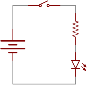
In our second circuit we have a 9V battery to supply the current and voltage, a switch to connect or disconnect the battry from the circuit, a resistor to limit the current through the Light Emitting Diode – LED to a safe working current and the LED which converts a potential difference across the diode semiconductor junction to photons, which are seen as light.
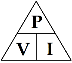
We can measure the current flowing in the circuit by using an ammeter and the voltage across any of the circuit components using a voltmeter, then calculate the Power or work being done in the circuit using the DC Power Formula P(watts) = V(Volts) x I(amps).
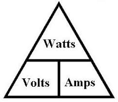
The relationship between Power in Watts, Voltage in Volts and Current in Amps is show in the Power Triangles above.
You can use a DC power calculator such as the one in ElectroDroid to simplify calculations.