Digital + Audio Microphone Module Z6336A
Altronics sell this as Z6336A Microphone D+A Module For Arduino , the antistatic packet it came in is labelled Funduino D+A Microphone Module. https://www.altronics.com.au/p/z6336a-microphone-d-a-module-for-arduino/
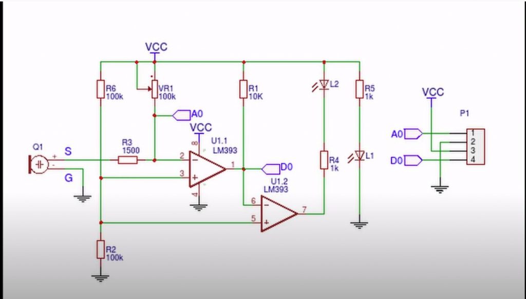
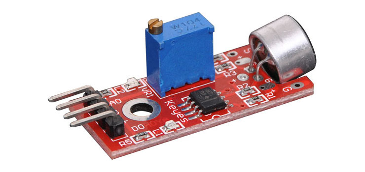
This version has a 4 pin 0.1 ” pitch right angle header. There is a power LED, a multi turn trim pot that sets the digital output threshold level for the pin D0 and the LM393 comparator output has a status LED.
The circuit board has a Keyes label and is also known as Keyes Sound Detection Module KY-038 and Keyes Ky-037. The 4 pin version has audio and digital output, the 3 pin version has digital output only.
Supply voltage 3 – 5V DC. M3 mounting hole. Data sheet with sketches https://www.mantech.co.za/Datasheets/Products/KY0037-190815A.pdf
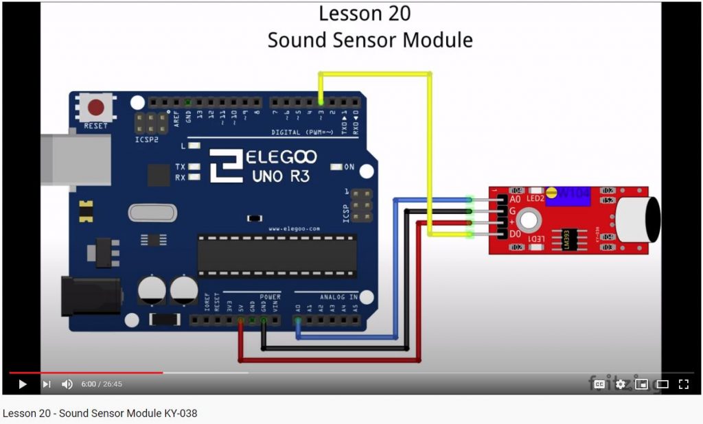
Pin 1 AO Analog output
Pin 2 Ground
Pin 3 +3 – 5V DC
Pin 4 DO Digital output
There are several limitations with using this sensor module:
The Arduino analog input needs to be biased at 2.5V DC to allow the maximum AC voltage swing, but the DC voltage on the A0 pin is varied by the D0 comparator adjust. If the multi turn trim pot is adjusted anto clockwise until the comparator LED goes out, the DC voltage on the A0 pin is about 2.5V DC.