WAAPA Lighting Buzz Box Project for First Year Lighting students is a practical example of a DC circuit that consists of a 9V battery, a buzzer, an LED, a switch and a set of test contacts that are housed in a small Jiffy box, that allows a student to test the lamp in a theatre light when rigging. The test contact spacing is suitable for the active and neutral pins of an Australian three pin plug, or the lamp pins.
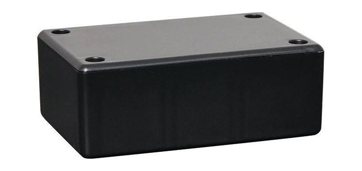
The Buzz Box uses an ABS (Acrylonitrile butadiene styrene) plastic that is impact resistant and tough, but can be easily drilled or cut. It is an insulator and can be damaged by heat. The Buzz Box uses an Altronics H0205 UB5 (82Lx54Wx30Hmm) external dimensions.
When working out where to locate the components on the plastic box, you need to have the measurements of all of the components that will be mounted inside of the box.
You can use a small pair of side cutters to remove the printed circuit guide tabs inside to provide more space.
The two m3 screws are usually mounted on one end of the box, so that when the box is help in your hand, the two screws or terminals, will be facing towards the lamp or plug to be tested. The spacing of the screws is determined by the spacing of the most common lamp you will test, in this case GY9.5 or GX9.5 , which is 9.5mm. This spacing will also suit a three pin mains plug.
The hole spacing is 9.5mm but when you add the width of the m3 screw head, the contacts will work with a range of spacings. To make it easier to mark out, use 10mm hole spacings.
Steel washers are used to help prevent the screw heads from damaging the soft ABS plastic, and also increases the contact area of the screw heads.
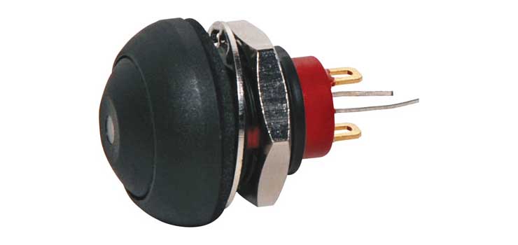
You can choose the type of switch that suits your work method. A momentary switch will extend the battery life as the battery is only connected when the switch is held down. It is low profile and easy to mount as it uses a round hole. It is usually mounted on the side of the box where it is easily operated by your thumb.
A rocker switch can be switched ON or OFF. It is used when you want to turn something on and leave it on for a while. As current only flows through the circuit when a seviceable lamp is bridging the contacts, the need for a switch is optional, unless they contacts are shorted out by something else.
A toggle switch can be switched ON or OFF. It is used when you want to turn something on and leave it on for a while. There are two styles of lever, thin rod or flat. The flat or paddle style is easier to operate due to the wider contact area, but can be damaged.
The LED emitter can be mounted on the opposite end of the box to the contacts, or on the top lid, so it is easily seen when using the buzz box, or on the same end as the contacts. Try the samples to see which one suits you. You need to measure the diameter of the lens of the LED to determine what size hole to drill. There is no mounting hardware supplied with the LED so it will have to be secured or glued to the box.
Wires will have to be soldered to the LED terminals. If you look at the terminals, there will be an indication of which terminal is the cathode. For the 3W LED we are using, there is a small square hole punched in one of the leads to indicate it is the cathode. For the 5mm LED the shorter lead is the cathode.
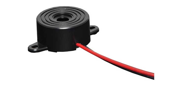
There is a choice of two different buzzers, the S6100 mechanical buzzer and the S6109 piezo buzzer. Both have tab mountings or can be glued inside the box. You can use a neutral cure silicon sealant like Selleys Roof & Gutter or a hot glue gun.
The buzzer opening will need to face into the box so the sound is louder, so use the tabs to mount it.
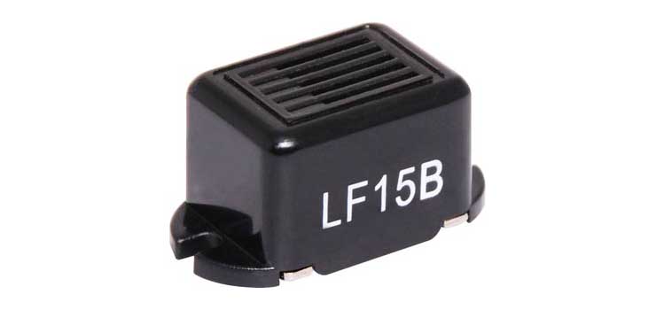
The S6100 Mechanical Chassis Mount Buzzer is polarity conscious so the Red lead has to go to positive voltage and the Black lead has to go to negative voltage. SPL Output: 75dB @ 20cmFrequency: 400Hz ± 100HzSupply Voltage: 9 – 15V DCCurrent: 25mA @ 12V DCFlyleads: 120mm15.5mm height
Use a pencil and ruler to mark out centre lines on both ends of the box
On one end on the box, mark out the position for the two screw holes, 5mm either side of the centre. Check your pencil marks to make sure the screw holes will be 10mm apart, which is suitable for GY9.5 lamps
Mark the hole positions using a centre punch. This helps guide the drill bit accurately onto the correct position. Drill bits can wander or move due to drill spindle wobble or incorrectly sharpened drill bits.
Put on safety glasses, put an m3 drill bit or a step drill with an m3 step into the drill press chuck. Tighten the drill chuck using the chuck key, unless it is a keyless chuck. Place the box in the centre of the drill vice with the end facing upwards. The drill press vice allows for more accurate work and improves safety as your hand is not near the rotating drill when the hole is drilled. You may have to raise or lower the drilling table using the locking handle and height handle so the box is positioned about 10mm below the drill bit. Position the drill vice so the drill bit makes contact with the centre punch mark.
Turn the drill on by pushing in the green start button, then lower the drill using the handle to drill the first hole. If you are using a step dill make sure you only use the first m3 step. Turn the drill off, reposition the drill vice so the box is positioned for the second hole. Turn the drill on, drill the second hole, then turn the drill off.
Remove the box from the vice, place the two m3 posidrive screws and washers in the holes to check your work progress.
Shown are two different switch positions. I first put it in the centre of one side, then tried it to one end, so the buzzer could mount on the same side, to leave more space for the battery.
The printed circuit board guides need to be cut away from where the buzzer is going to be mounted, so the buzzer can mount flat on the side of the jiffy box.
The switch has been mounted and the tabs cut away from the side, ready for the buzzer to be mounted.
The switch is centered between the printed circuit board mounting tabs and the support rib above it, so the switch securing nut has clearance.
The buzzer has been mounted on the side of the jiffy box using two 2.4mm pop rivets, as the pop rivet head does not stick out as far as an m2 or m2.5 screw. It also gives you experience with trying different types of fasteners. 2.4mm pop rivets have to be bought from specialty fasteners such as CFI Fasteners in Malaga or RS Components. The pop rivet has to have a washer put on it to squash down onto the soft plastic of the buzzer mounts.
Alternatively, the buzzer can be glued in place using silastic or similar glue. Super glue is not suitable as the buzzer is not flush with the side of the jiffy box.
The LED can be mounted in the centre of the end of the jiffy box by dilling a 5mm hole in the centre, then glue the LED in place using super glue, with the anode facing towards the switch and buzzer and the cathode (square mark) facing the blank jiffy box wall.
Wires will have to be soldered onto the LED terminals.
The buzzer is polarity sensitive, so it will only buzz if the current flows in the correct direction.
Solder the buzzer Red wire to the LED Anode and the buzzer Black wire to the switch contact.
Solder a short wire from the second switch contact, to the closest contact terminal. Do not use red or black sheathed wire, as they are reserved for positive and negative.
Solder the Red of the Battery Snap to the LED Cathode and the Black of the Battery Snap to the second contact terminal.
Check your wiring, then insert a battery so you can test your Buzz Box for correct operation.
With a fully charged 9V battery, the voltage across the buzzer is 6.9V so the buzzer will not be very loud, as the operating voltage is 9 – 15V DC. The buzzer limits the LED current to 12 mA so the LED will not be very bright.
Once testing put thread locker on the contact terminal nuts.
When you are ready to close the Jiffy Box up, use some foam or bubblewrap to stop the battery moving about, but do not put too much in, the lid should close flat.
The LED can be fitted to the opposite end of the jiffy box or it can be mounted on the same end as the contacts so you can see the LED light up when you make contact with a serviceable lamp.
The right hand jiffy box has been fitted with a high intensity 5mm Z0877B 25000mcb warm white LED, to try different styles. The LED has been glued into a 5mm hole with super glue.
The lid of the Buzz Box has been marked out so the belt clip will be in the centre of the lid. The screw holes are 20mm up from the centre of the lid and 10mm either side of the centre.
The belt clip screws are screwed from the inside of the lid, as shown.