Working 4 channel Demux using DIP switch addressing 11 February 2021. scroll down for details and sketch codes for the different elements of the completed projects
What is 0 – 10V requirements – voltage, current drive, blocking diodes.
4 Channel DMX Demux – modifying the DmxSerialRcv program for 4 output channels.
DIPSWaddress10Inverted – cheapest, easiest, most compact way of setting DMX start address.
Choosing an RS485 transceiver – there are a lot of choices to be made !
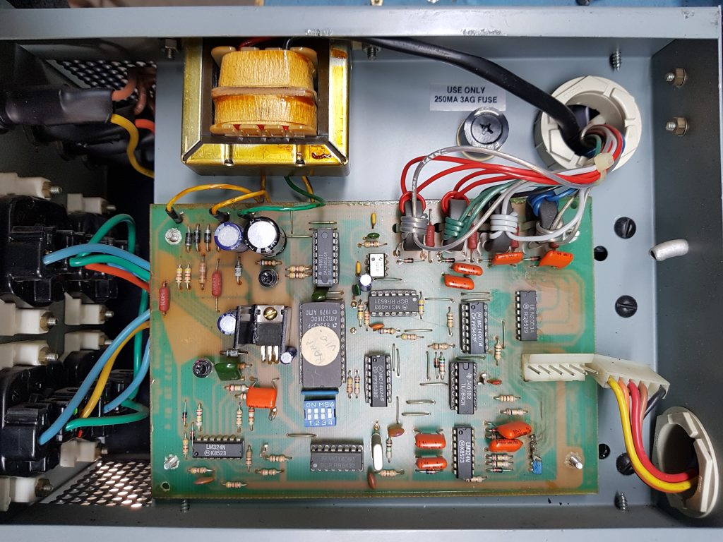
MultiPak1 Jands Multipak Analogue Dimmer Service manual with schematics. http://www.theatrelightingworkshops.com/wp-content/uploads/2020/05/MultiPak.pdf
These dimmers were originally designed to be used with analogue lighting desk, then were used with a DMX to 10V analogue demultiplexer.
You can fit an Arduino DMX to 10V demultiplexer inside the right hand control module.
Each 4 channel dimmer module is designed to be fed from a 32 Amp single phase feed, has a DC power supply to power the circuit electronics, so is a stand alone module.
Similar design dimmer racks were made by Rank Strand Australia.


Strand Minipak Analogue Dimmer Maintenance Handbook
http://www.theatrelightingworkshops.com/wp-content/uploads/2020/05/Minipak-Maintenance-Handbook.pdf

Design Notes – What is 0 – 10V requirements
The ANSI E1.3 -2001 0-10V standard can be downloaded from https://tsp.esta.org/tsp/documents/published_docs.php
6.1.2 Current source capacity and output impedance (Transmitter)
Controllers or output devices should have a low output impedance to minimize loading effects.
Passive controllers, with unbuffered outputs, shall use potentiometers with a resistance value of 10K
ohms or less (which yields an output impedance of 2.5K ohms or less). Active controllers with buffered
outputs shall have a source impedance of 100 ohms or less and be capable of continuously sourcing at least 2.0 milliamperes without dropping below 10 V. Controllers or output devices shall have a
sinking impedance greater than 50K ohms, even when power is removed.
The more current source capacity a controller has the more receivers it can drive. (More is better).
The manufacturers’ specifications shall state the output capability as both the maximum source
current and the lowest load impedance at which an output of 10.0 volts can be maintained.
6.1.3 Diode protection
Controllers and output devices shall be provided with a blocking diode (or equivalent circuit) such that
each output presents an open circuit (50K ohms or more) to any source of voltage more positive than
itself. The operation of the product shall be unaffected by the presence of such a more positive
voltage. This diode or equivalent circuit shall be capable of blocking voltages of +30 D.C. volts or
greater. The blocking diodes allow multiple controllers or output devices to be paralleled to control the same
dimmers or receiving devices. Whichever controller has the higher control voltage has control of that
channel. This method of control is commonly referred to as “highest takes precedence” or “pile-on.”
Downloaded from TSP.ESTA.ORG. Dowload sponsored by Prosight Specialty Insurance.
A 4 Channel DMX Demux can be made using the DMX Serial library located at http://www.mathertel.de/Arduino/DMXSerial.aspx .
Download the Arduino library using the IDE Library Manager, then for a DMX demux, open up File>Examples>DMXSerial>DmxSerialRecv .
The example is a 3 channel DMX serial receiver used to control RGB LED’s.
This sketch uses the Arduino Tx and RX pins for DMX communication, so you will need to unplug your shield to allow the Arduino to use the serial USB comms with your computer, then plug the shield back on to test the DMX response.
You need to change the program to add a fourth channel and renumber output pins to simplify wiring.
const int RedPin = 11; // PWM output pin for Red Light.
const int GreenPin = 10; // PWM output pin for Green Light.
const int BluePin = 9; // PWM output pin for Blue Light.
const int BluePin = 6; // PWM output pin for White Light.
The DMX channel numbers are set in this portion of code:
if (lastPacket < 5000) {
// read recent DMX values and set pwm levels
analogWrite(RedPin, DMXSerial.read(1));
analogWrite(GreenPin, DMXSerial.read(2));
analogWrite(BluePin, DMXSerial.read(3));
You can add a fourth receive channel with analogWrite(WhitePin, DMXSerial.read(4));
and other program aprts.
To make it a more practical project will allow for the DMX receive address to be set easily on the dimmer.
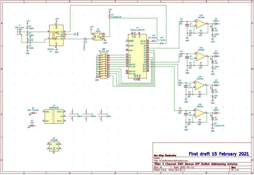
The PWM output of the Arduino has to be smoothed or integrated to make a DC voltage suitable for the analogue dimmer control inputs and the 5V output of the Arduino needs to be increased to the o – 10V range needed for the analogue dimmer using an op amp. The Jands dimmer module has a +/- 15V power supply so we can use a quard op amp such as TL094.
Circuit being drawn up.
Output of PWM pins goes to inputs of LM324 quad op amp using a single 12V power supply, having a gain of X2, input RC filter network of 10K resistor and a 1uF MKT capacitor. Basic low pass filter circuit. Diode steering on output. Need to add opto isolator and DC – DC converter for galvanic isolation.
DMX addressing options are:
DIP Switch – needs an Arduino input pin for every switch, not everyone can work out address using DIP switch. (use phone app). https://www.altronics.com.au/p/s3065-10-way-dip-switch/
DIPSWaddress10Inverted sketch code is easy to understand.
// Code for reading in the status of ten DIP Switches, if a switch in ON, a BCD weighted value is added to a total in variable startaddress.
// this is not efficient coding, but it is easy to read and understand the process.
// Modified by Don Allen on 9 Fedruary 2021
// This is part of DMX Demux which will use D0 for Serial Rx, D1 as Serial Tx, D6, D9, D10, D11 as PWM outputs for 0-10V DC outputs.
// Only 9 DIP Switches are needed to add up to 512, 10 DIP Switch packages are easier to get than 9 pin, so we have a spare for another function.
// This version uses PULLUP resistors in the Arduino so no resitors are needed on the DIP Switch
// The digitalRead has been swapped so the number value is read in when the switch is ON which is an active LOW.
// inputs from the dip switches
const int Input1 = 14; //A1 digital pin numbering
const int Input2 = 15; //A2 digital pin numbering
const int Input3 = 16; //A3 digital pin numbering
const int Input4 = 17; //A4 digital pin numbering
const int Input5 = 18; //A5 digital pin numbering
const int Input6 = 19; //A6 digital pin numbering
const int Input7 = 8; // digital pin numbering
const int Input8 = 7; // digital pin numbering
const int Input9 = 5; // digital pin numbering
const int Input10 = 4; // digital pin numbering
// initiallising the dip switch values to 0
int Dip1 = 0;
int Dip2 = 0;
int Dip3 = 0;
int Dip4 = 0;
int Dip5 = 0;
int Dip6 = 0;
int Dip7 = 0;
int Dip8 = 0;
int Dip9 = 0;
int Dip10 = 0;
int startAddress = 1; // lowest DMX address.
void setup () {
Serial.begin(9600); // Initiate Serial communication so we can print startaddress value to serial monitor to check wiring and sketch.
pinMode(Input1, INPUT_PULLUP);
pinMode(Input2, INPUT_PULLUP);
pinMode(Input3, INPUT_PULLUP);
pinMode(Input4, INPUT_PULLUP);
pinMode(Input5, INPUT_PULLUP);
pinMode(Input6, INPUT_PULLUP);
pinMode(Input7, INPUT_PULLUP);
pinMode(Input8, INPUT_PULLUP);
pinMode(Input9, INPUT_PULLUP);
pinMode(Input10, INPUT_PULLUP); // this is the spare DIP Switch
}
void loop() {
Serial.print(“DIP SWITCH address “);
Serial.println (startAddress);
delay (1000); // Delays stop the program so only suitable in this sketch. Do not use in DMXSerial
// translate the dip switches inputs into a number
if (digitalRead(Input1) == LOW) {Dip1 = 1;}
if (digitalRead(Input1) == HIGH) {Dip1 = 0;}
if (digitalRead(Input2) == LOW) {Dip2 = 2;}
if (digitalRead(Input2) == HIGH) {Dip2 = 0;}
if (digitalRead(Input3) == LOW) {Dip3 = 4;}
if (digitalRead(Input3) == HIGH) {Dip3 = 0;}
if (digitalRead(Input4) == LOW) {Dip4 = 8;}
if (digitalRead(Input4) == HIGH) {Dip4 = 0;}
if (digitalRead(Input5) == LOW) {Dip5 = 16;}
if (digitalRead(Input5) == HIGH) {Dip5 = 0;}
if (digitalRead(Input6) == LOW) {Dip6 = 32;}
if (digitalRead(Input6) == HIGH) {Dip6 = 0;}
if (digitalRead(Input7) == LOW) {Dip7 = 64;}
if (digitalRead(Input7) == HIGH) {Dip7 = 0;}
if (digitalRead(Input8) == LOW) {Dip8 = 128;}
if (digitalRead(Input8) == HIGH) {Dip8 = 0;}
if (digitalRead(Input9) == LOW) {Dip9 = 256;}
if (digitalRead(Input9) == HIGH) {Dip9 = 0;}
if (digitalRead(Input10) == LOW) {Dip10 = 512;}
if (digitalRead(Input10) == HIGH) {Dip10 = 0;}
startAddress = Dip1 + Dip2 + Dip3 + Dip4 + Dip5 + Dip6 + Dip7 + Dip8 + Dip9 + Dip10; // set the startAddress
}
Rotary BCD Switch or Push button thumbwheel switch – needs a lot of pins, but easy to set up addresses.
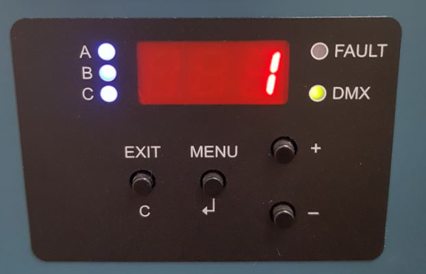
Using a 4 digit 7 segment display with SPI interface so only 2 digital pins needed for Arduino interface. Will need push button switches to set DMX address. This example is a Jands WMX dimmer. Using push button switches and a menu allow for options such as channel test functions. Need to write Address Set subroutine for Arduino, but easiest user interface.
DmxSerialRcv4ChannelAddressingPullUpResistors – putting it all together.
This sketch uses pins 1-9 on a DIP Switch to set the DMX receive address of a block of four channels. It is running on a Uno but will also work on a Nano with pin number changes.
Remember to remove the TX and RX jumpers on the DMX shield when downloading the sketch and put back to receive serial DMX data.
// – – – – –
// DmxSerial – A hardware supported interface to DMX.
// DmxSerialRecv4Challel.ino: Sample DMX application for recieving 4 DMX values:
// address 1 (red) -> PWM Port 3
// address 2 (green) -> PWM Port 9
// address 3 (blue) -> PWM Port 10
// address 4 (white) -> PWM Port 11
// Documentation and samples are available at http://www.mathertel.de/Arduino/DMXSerial.aspx
// 09.02.2021 modified for four DMX channels by Donald Allen.
// DMX Start Address set in DIP Switches, variable startaddress used for start adrress of four channels.
// Used PullUpResistors to replace 10 resistors on circuit board. digitalRead(input ) LOW is now value.
// changed port 6 to port 3 so all PWM outputs are 490Hz
#include
// Constants for demo program
const int RedPin = 3; // 490Hz PWM output pin for Red Light.
const int GreenPin = 9; // 490Hz PWM output pin for Green Light.
const int BluePin = 10; // 490Hz PWM output pin for Blue Light.
const int WhitePin = 11; // 490Hz PWM output pin for White Light.
#define RedDefaultLevel 000 //want dimmer channels to default to Off.
#define GreenDefaultLevel 000 //want dimmer channels to default to Off.
#define BlueDefaultLevel 000 //want dimmer channels to default to Off.
#define WhiteDefaultLevel 000 //want dimmer channels to default to Off.
// inputs from the dip switches
const int Input1 = 14; //A1 digital pin numbering
const int Input2 = 15; //A2 digital pin numbering
const int Input3 = 16; //A3 digital pin numbering
const int Input4 = 17; //A4 digital pin numbering
const int Input5 = 18; //A5 digital pin numbering
const int Input6 = 19; //A6 digital pin numbering
const int Input7 = 8; // digital pin numbering
const int Input8 = 7; // digital pin numbering
const int Input9 = 5; // digital pin numbering
const int Input10 = 4; // digital pin numbering
// initiallising the dip switch values to 0
int Dip1 = 0;
int Dip2 = 0;
int Dip3 = 0;
int Dip4 = 0;
int Dip5 = 0;
int Dip6 = 0;
int Dip7 = 0;
int Dip8 = 0;
int Dip9 = 0;
int Dip10 = 0;
int startAddress = 1; // lowest DMX address.
void setup () {
DMXSerial.init(DMXReceiver);
pinMode(Input1, INPUT_PULLUP);
pinMode(Input2, INPUT_PULLUP);
pinMode(Input3, INPUT_PULLUP);
pinMode(Input4, INPUT_PULLUP);
pinMode(Input5, INPUT_PULLUP);
pinMode(Input6, INPUT_PULLUP);
pinMode(Input7, INPUT_PULLUP);
pinMode(Input8, INPUT_PULLUP);
pinMode(Input9, INPUT_PULLUP);
pinMode(Input10, INPUT_PULLUP); // this is the spare DIP Switch
// set some default values
DMXSerial.write(1, 0); //want dimmer channels to default to Off.
DMXSerial.write(2, 0); //want dimmer channels to default to Off.
DMXSerial.write(3, 0); //want dimmer channels to default to Off.
DMXSerial.write(4, 0); //want dimmer channels to default to Off.
// enable pwm outputs
pinMode(RedPin, OUTPUT); // sets the digital pin as output
pinMode(GreenPin, OUTPUT);
pinMode(BluePin, OUTPUT);
pinMode(WhitePin, OUTPUT);
}
void loop() {
// translate the dip switches inputs into a number
if (digitalRead(Input1) == LOW) {Dip1 = 1;}
if (digitalRead(Input1) == HIGH) {Dip1 = 0;}
if (digitalRead(Input2) == LOW) {Dip2 = 2;}
if (digitalRead(Input2) == HIGH) {Dip2 = 0;}
if (digitalRead(Input3) == LOW) {Dip3 = 4;}
if (digitalRead(Input3) == HIGH) {Dip3 = 0;}
if (digitalRead(Input4) == LOW) {Dip4 = 8;}
if (digitalRead(Input4) == HIGH) {Dip4 = 0;}
if (digitalRead(Input5) == LOW) {Dip5 = 16;}
if (digitalRead(Input5) == HIGH) {Dip5 = 0;}
if (digitalRead(Input6) == LOW) {Dip6 = 32;}
if (digitalRead(Input6) == HIGH) {Dip6 = 0;}
if (digitalRead(Input7) == LOW) {Dip7 = 64;}
if (digitalRead(Input7) == HIGH) {Dip7 = 0;}
if (digitalRead(Input8) == LOW) {Dip8 = 128;}
if (digitalRead(Input8) == HIGH) {Dip8 = 0;}
if (digitalRead(Input9) == LOW) {Dip9 = 256;}
if (digitalRead(Input9) == HIGH) {Dip9 = 0;}
if (digitalRead(Input10) == LOW) {Dip10 = 512;}
if (digitalRead(Input10) == HIGH) {Dip10 = 0;}
startAddress = Dip1 + Dip2 + Dip3 + Dip4 + Dip5 + Dip6 + Dip7 + Dip8 + Dip9 + Dip10; // set the startAddress
// Calculate how long no data backet was received
unsigned long lastPacket = DMXSerial.noDataSince();
if (lastPacket < 5000) {
// read recent DMX values and set pwm levels
analogWrite(RedPin, DMXSerial.read(startAddress)); // DIP Switch start address
analogWrite(GreenPin, DMXSerial.read(startAddress +1)); // DIP Switch start address +1
analogWrite(BluePin, DMXSerial.read(startAddress + 2)); // DIP Switch start address +2
analogWrite(WhitePin, DMXSerial.read(startAddress + 3)); // DIP Switch start address +3
} else {
// Show pure red color, when no data was received since 5 seconds or more.
analogWrite(RedPin, RedDefaultLevel);
analogWrite(GreenPin, GreenDefaultLevel);
analogWrite(BluePin, BlueDefaultLevel);
analogWrite(BluePin, BlueDefaultLevel);
} // if
}
// End.
Choosing an RS485 transceiver
a transceiver ic is needed to convert the serial output or input data from the Arduino to a voltage suitable for the RS485 balanced line.
The industry standard was the 75176 which is still in common use. The SN75176A combines a 3-state differential line driver and a differential input line receiver, both of
which operate from a single 5-V power supply. The
driver and receiver have active-high and active-low
enables, respectively, that can be externally
connected together to function as a direction control.
The driver differential outputs and the receiver
differential inputs are connected internally to form
differential input/output (I/O) bus ports that are
designed to offer minimum loading to the bus
whenever the driver is disabled or VCC = 0. These
ports feature wide positive and negative commonmode voltage ranges making the device suitable for
party-line applications.
The driver is designed to handle loads up to 60 mA of
sink or source current. The driver features positiveand negative-current limiting and thermal shutdown
for protection from line fault conditions. Thermal
shutdown is designed to occur at a junction
temperature of approximately 150°C. The receiver
features a minimum input impedance of 12 kΩ, an
input sensitivity of ±200 mV, and a typical input
hysteresis of 50 mV
I will use this for first design, then replace with SN65HVD1780P which are not held in stock in Australia by RS components.
The MAX485 is a lower power transceiver that has a lower data rate.
RS485 receivers can output false data when the differential voltage is between +200mV and -200mV. This can cause false data or flickering of lights, so a failsafe design uses 3 resistors on the input to the transceiver, the Line Termination resistor, the pullup failsafe resistor and the pulldown failsafe resistor.
The SN65HVD1780P is a RS-485 Fault-protected Transceiver designed to survive over-voltage faults such as direct shorts to power supplies, mis-wiring faults, connector failures, cable crushes and tool mis-applications. The device is also robust to ESD events with high levels of protection to the human-body-model specification. The SN65HVD178x device combines a differential driver and a differential receiver, which operate from a single power supply. In the SN65HVD1782, the driver differential outputs and the receiver differential inputs are connected internally to form a bus port suitable for half-duplex (two-wire bus) communication. This port features a wide common-mode voltage range, making the device suitable for multipoint applications over long cable runs. This device is pin-compatible with the industry standard SN75176 transceiver, making them drop-in upgrades in most systems.
The MAX3440E–MAX3444E fault-protected RS-485 and
J1708 transceivers feature ±60V protection from signal
faults on communication bus lines. Each device contains
one differential line driver with three-state output and one
differential line receiver with three-state input. The 1/4-unitload receiver input impedance allows up to 128 transceivers on a single bus. The devices operate from a 5V
supply at data rates of up to 10Mbps. True fail-safe inputs
guarantee a logic-high receiver output when the receiver
inputs are open, shorted, or connected to an idle data line
Page updated 15 February 2021 – Draft schematic to get it started.
Updated section on choosing RS485 transceiver.
Previous updates: changed DIP Switch addressing to remove need for 10 pullup resistors.
Used LM324 for single 12V supply X2 gain low pass filter for 0 – 10V output. Output goes to 0V.
Added DIP Switch decoder sketch tp allow external setting of DMX address.
Got DmxSerialRCV working then added fourth channel4