The design discussion for this planetarium was to have no moving parts, so in order for the stars to move around the sky, the Arduino will fade between the 1W LED’s so an apparent shift or movement of the stars will occur.
A mesh or punched collander will be tried as the mask to create the star patterns.
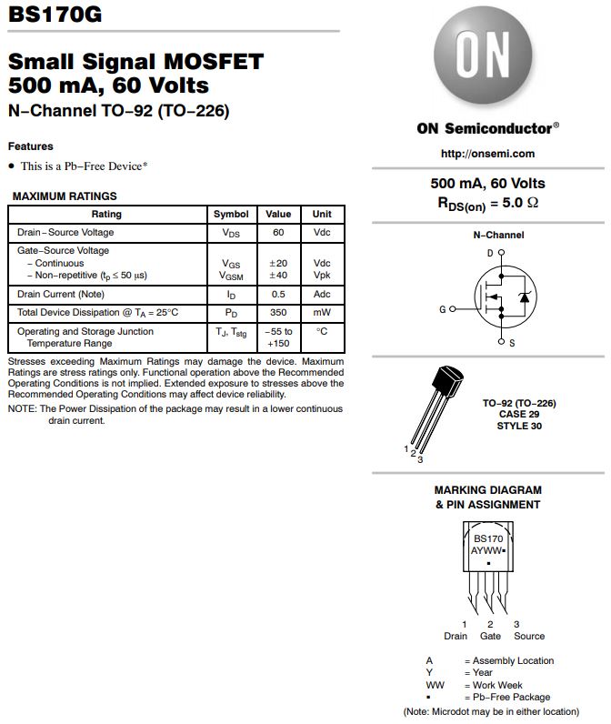
Power supply requirements – want to avoid dumping excess heat in resistors, as RGB LED emitters need 2.4Vf for Red, 3.4Vf for Green and Blue, a 5V supply will waste the least amount of power in the emitter resistors.
WARNING – Mega needs +5V so external +5V supply needs to be connected by the shield to a +5V pin and the 0V of external +5V supply connected to Mega GND. You cannot use the 2.1mm power in connector as it has a low voltage drop schottky diode in sereis for reverse polarity protection and a low dropout voltage regulator in series, so there will not be a high enough voltage for the Mega to run reliably.
You need to unplug the LED driver shield when you want to connect the Mega to the computer USB or use a jumper shunt for +5V isolation.
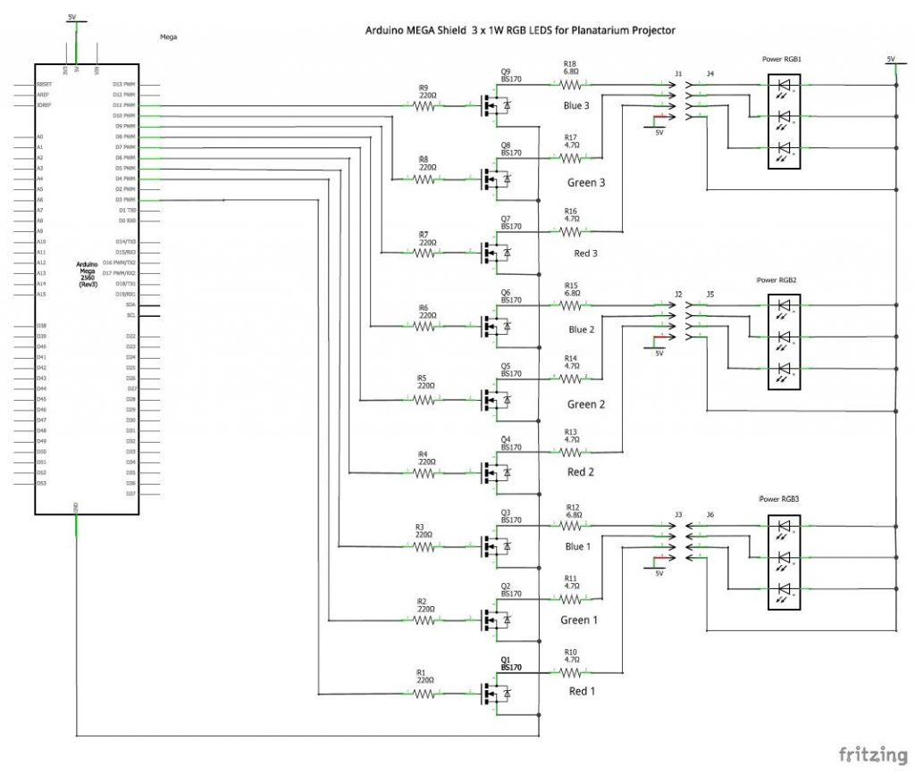
Fritzing has been used to draw a schematic of the Arduino MEGA with an N channel FET driver for each of the PWM outputs.
A 220 ohm resistor in series with each FET base provides current limiting protection for the Mega digital output ports.
The Drain output of the FET has a compact 0.6W current limiting resistor for the 1W LED emitter. With a VDS of 5V and IF=350mA Vf(R) Typ. 2.4V R= 7R5 .9W – use two 15R .6W in parallel Vf(G) Typ. 3.4V R= 4R5 .56W Vf(B) Typ. 3.4V R= 4R5 .56W
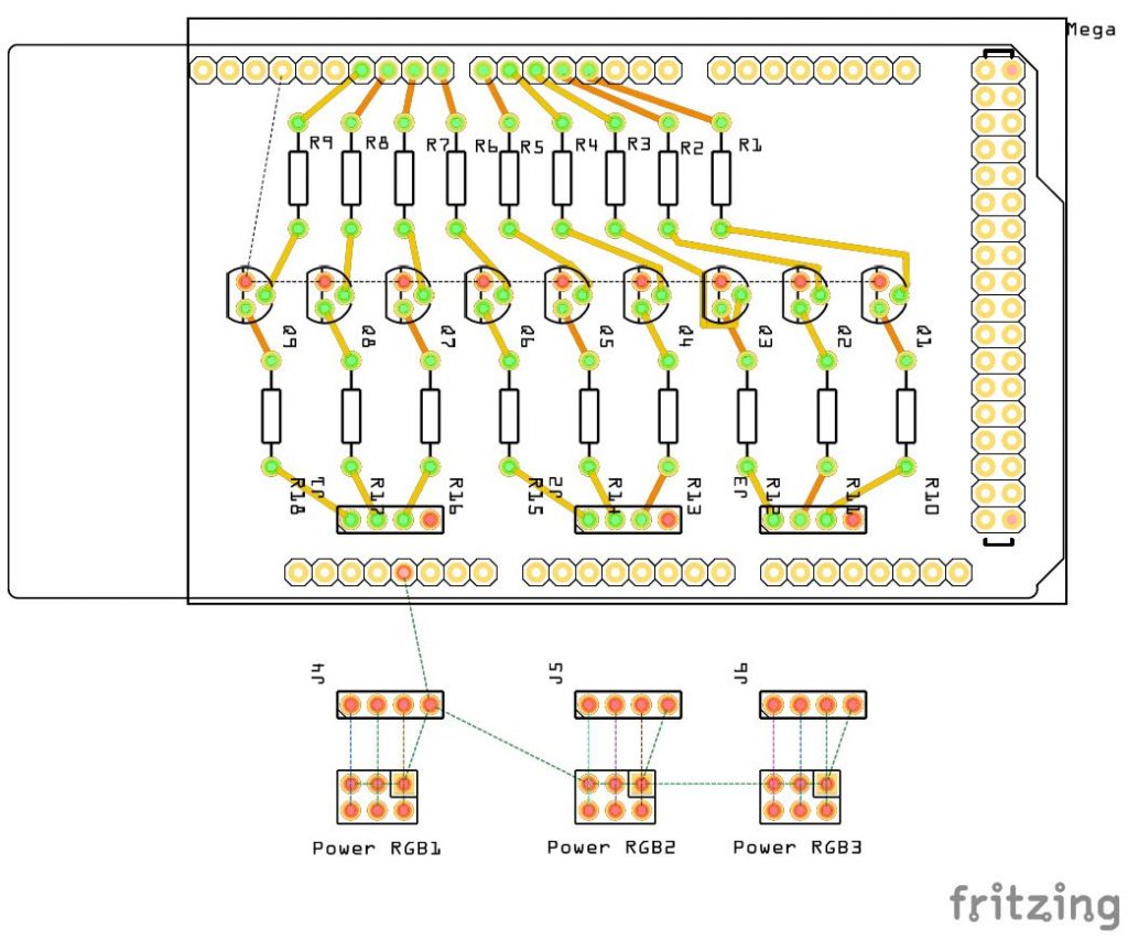
Once the schematic has been drawn and all errors (red bits) fixed, we can look at the pcb layout to help visualise if all of the parts will fit on the Mega shield. The pcb has been autorouted to show connections, except for the common ground on the Source connections which has been left unrouted for clarity of the other connections.