Still being debugged on Saturday 13 June 2020
the ATmega328 microcontroller used in the Arduino has 6 analog input pins that share 1 ADC (Analog to Digital Converter) converter. The 6 input pins are connected to a multiplexer which switches one of the 6 analog inputs to the ADC in order to get a reading. The ADC needs time to take the samples and store them into a register, before sampling the next input. To read 2 or more analog inputs in a sketch, read an analog input, use a 10ms pause while the analog input is switched and stabilises, then read that analog input a second time, then use the second reading. Then do the same steps for the other analog inputs you want to use.
When we want to increase the number of analog inputs by using input multiplexers such as the CD4051 we need to allow time for these additional inputs to be read.
Single LDR analog input example.
We are going to explore the operation of Arduino analog inputs by using a Light Dependent Resistor or LDR which changes resistance depending on how much light falls on it. The brighter the light the lower the resistance, the lower the light level, the higher the resistance. We are going to start by opening up the Arduino IDE program and using the AnalogReadSerial program which is located on the top menu bar at File>Examples>01Basics>AnalogReadSerial .
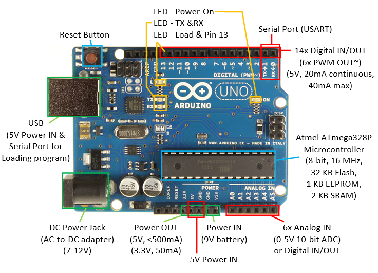
With our Arduino Uno plugged into a computer USB port the green power LED should be on. Select Tools on the top menu and you should see
Board:”Arduino Uno”
Port:”COM6 (Arduino Uno)”
Get Board Info
Your COM port number may be different but there needs to be a COM port number and the type of Arduino board you are using. If there is no Arduino board shown, select the Board drop down menu to see what port your Arduino board is on.
Next we will load the AnalogReadSerial sketch by selecting the Right Arrow Upload symbol. The lower menu bar will show Compiling sketch … then Uploading … then Done uploading.
While this is happening the Tx and Rx LED’s on the Arduino board will flash to show that serial communications is occurring as the program is loaded and the Arduino board acknowledges what is happening, then the Tx LED stays on and the LED 13 comes on
Now use your breadboard to connect one leg of your LDR to +5V, the other leg to one leg of a 47K resistor, the other leg of the 47K resistor to Ground, use a jumper wire to connect the junction of the LDR and 47K resistor to the analog input A0.
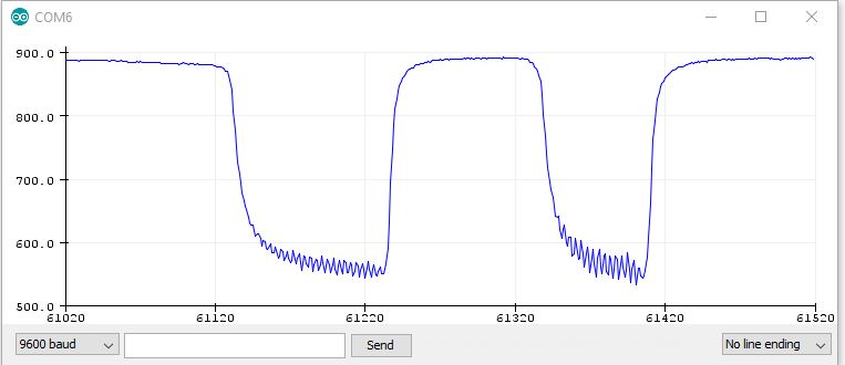
Now on the top menu bar select Tools>Serial Plotter to see a graphical plot of the voltage on the analog input A0. Now put your finger over the top of the LDR, which will increase the resistance of the LDR, which will change the voltage divider ratio, this will increase the voltage across the LDR, so the voltage across the resistor will decrease and the serial plotter graph will drop in level. This plot shows several quick finger taps.
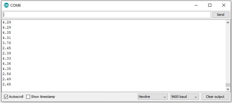
To change the display from seeing a Plot to reading a Voltage, keep the same circuit, and load File>Example>01.Basics>ReadAnalogVoltage , Upload the file and select Tools>Serial Monitor to see the voltage on the analog input A0. If you get an error message Serial monitor not available while plotter is open, go to Tools>Serial plotter, close the Serial plotter, then you can open the Serial monitor. You will see a fast string of voltages, if you want to slow it down, add the line delay(500); at the end of your program and upload it to the board. I had to do this to get several different voltage readings on the serial monitor for my finger taps.
Now we want to see an LED change state when we cover the LDR. Keep the same circuit, Load the File>Examples>05.Control>IfStatementConditional , Upload to your board. Select Tools>Serial monitor to see a fast scrolling string of numbers. If you put your finger on the LDR the numbers will change, but the LED 13 stays ON as the threshold is set too high for our LDR circuit. They normally use a potentiometer with this example sketch.
Change the threshold to 700 then Upload the sketch, reselect Serial monitor and you will see the LED 13 go OFF and the level increase when you put your finger on the LDR. (The value of 700 was chosen after testing several different LDR’s)
Next step is to duplicate the LDR and 47K resistor circuit five more times, so we can connect jumpers from the voltage dividers to analog inputs A1 to A5, so we now have six analog inputs connected. You can connect the A0 jumper to any of the six voltage dividers to see if the LED goes out, to test the accuracy of your wiring.
WE want to change the LED to come ON when the LDR is covered, but don’t want to save any changes to this IfStatementConditional example file, so we need to save the new file as SixInputLDR using File>Save As… then type SixInputLDR in the highlighted box, then Save.
Change the second and third comment line to read It reads the voltage of a LDR connected to an analog input and turns ON an LED if the light falling on the LDR goes below a certain threshold level to accurately describe what we want to achieve with this sketch.
Change the circuit description to read:
– LDR
One leg of the LDR goes to +5V, other leg of LDR goes to one leg of 47K resitor and analog pin 0. Other side of 47K resistor goes to ground.
– LED connected from digital pin 13 to ground.
Now change the condition statement to read
// if the analog value is high enough, turn off the LED:
if (analogValue > threshold) {
digitalWrite(ledPin, LOW);
} else {
digitalWrite(ledPin, HIGH);
Upload the sketch to your board and you now have a sketch that turns an LED on when you cover the LDR with your finger, or the ambient light level goes dark enough for the LED to come on.
Now we modify the constants const section at the start of the sketch to increase the number of analog inputs to 6. Note that the first analog input is a0 and the sixth analog input is A5.
I copied the first line, pasted it 5 times and then changed the analog input number A1 – A5 and description note to // pin that LDR is attached to. You can just copy and paste this code if you want to:
const int analogPinA0 = A0; // pin that LDR1 is attached to
const int analogPinA1 = A1; // pin that LDR2 is attached to
const int analogPinA2 = A2; // pin that LDR3 is attached to
const int analogPinA3 = A3; // pin that LDR4 is attached to
const int analogPinA4 = A4; // pin that LDR5 is attached to
const int analogPinA5 = A5; // pin that LDR6 is attached to
Next I added 5 more LED’s by adding the code
const int ledPin13 = 13; // pin that the LED is attached to for A0 LDR1
const int ledPin12 = 12; // pin that the LED is attached to for A1 LDR2
const int ledPin11 = 11; // pin that the LED is attached to for A2 LDR3
const int ledPin10 = 10; // pin that the LED is attached to for A3 LDR4
const int ledPin9 = 9; // pin that the LED is attached to for A4 LDR5
const int ledPin8 = 8; // pin that the LED is attached to for A5 LDR6
I expanded the comment to add the number of the LED that was for the analoge input. When adding your 6 LED’s to the digital outputs remember to add a 220 ohm resistor in series with each LED as a current limiter.
Then we need to set up six digital output pins for the LED’s
pinMode(ledPin13, OUTPUT);
pinMode(ledPin12, OUTPUT);
pinMode(ledPin11, OUTPUT);
pinMode(ledPin10, OUTPUT);
pinMode(ledPin9, OUTPUT);
pinMode(ledPin8, OUTPUT);
// read the value of the LDR:
int analogValueA0 = analogRead(analogPinA0);
delay(5); // delay in between reads for stability was 1
int analogValueA1 = analogRead(analogPinA1);
delay(5); // delay in between reads for stability was 1
int analogValueA2 = analogRead(analogPinA2);
delay(5); // delay in between reads for stability was 1
int analogValueA3 = analogRead(analogPinA3);
delay(5); // delay in between reads for stability was 1
int analogValueA4 = analogRead(analogPinA4);
delay(5); // delay in between reads for stability was 1
int analogValueA5 = analogRead(analogPinA5);
delay(5); // delay in between reads for stability was 1
The next section of code turns the LED on if the LDR is covered.
// if the analog value is high enough, turn on the LED:
if (analogValueA0 > threshold) {
digitalWrite(ledPin13, HIGH);
} else {
digitalWrite(ledPin13, LOW); // LED 13 works
}
if (analogValueA1 > threshold) {
digitalWrite(ledPin12, HIGH);
} else {
digitalWrite(ledPin12, LOW); // This flashes LED’s 2-6
}
if (analogValueA1 > threshold) {
digitalWrite(ledPin11, HIGH);
} else {
digitalWrite(ledPin11, LOW);
}
if (analogValueA1 > threshold) {
digitalWrite(ledPin10, HIGH);
} else {
digitalWrite(ledPin10, LOW);
}
if (analogValueA1 > threshold) {
digitalWrite(ledPin9, HIGH);
} else {
digitalWrite(ledPin9, LOW);
}
if (analogValueA1 > threshold) {
digitalWrite(ledPin8, HIGH);
} else {
digitalWrite(ledPin8, LOW);
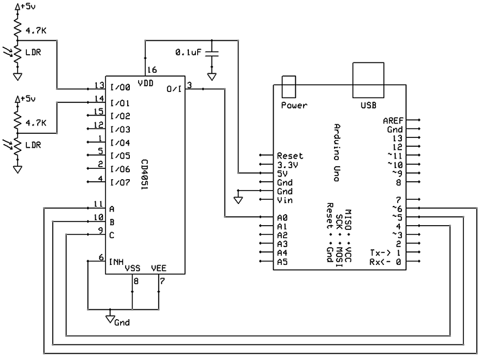
The Arduino has 6 analog inputs. You can increase the number of analog inputs by using multiplexers such as the CD4051 that can switch one of the 8 inputs to the common output.
This example from Nick Gammon http://www.gammon.com.au/forum/?id=11976 shows how to connect a CD4051 mutiplexer and has sample code for an Arduino.
If you have a CD4051 mutliplexer fro each Arduino analog input, you can increase the number of input channels to 48, with some limitations.
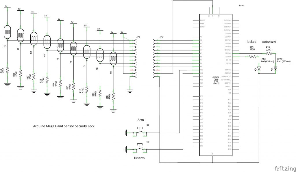
Using a Mega expands the number of analog inputs to a maximum of 16. 9 inputs are used for hand sensors and 2 inputs are used to arm or disarm the lock. These two inputs are set to INPUT and HIGH to use the pullup resistors built into the arduino. In this example they are active LOW logic.
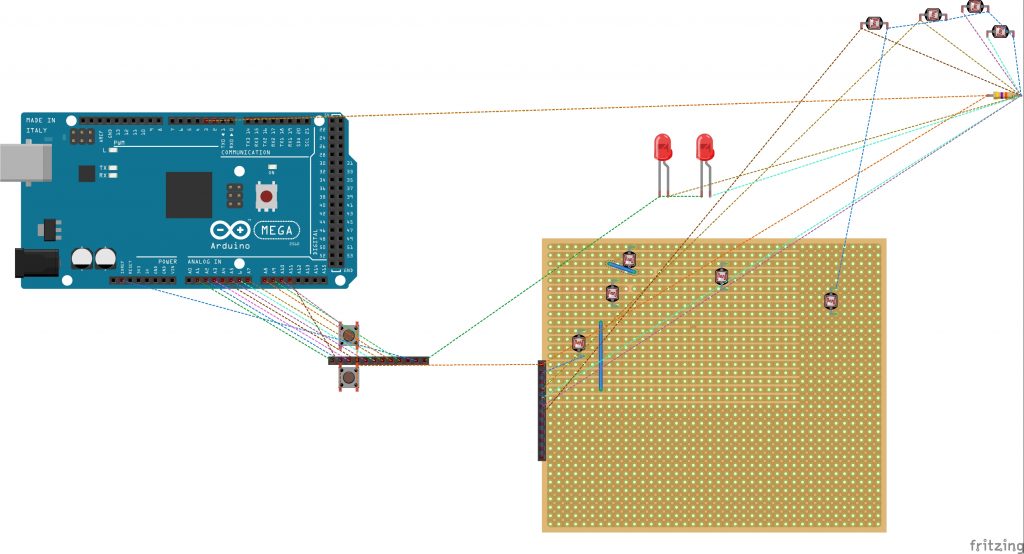
Drawing the breadboard in fritzing can be very time consuming when using a large number of holes. The refresh time for this size image is 30 seconds which is not practical when trying to move components.
Page updated 27 September 2020